


Solution to vibration of petroleum gear pump
2024-09-09 07:36:23
1、 Solution to vibration of gear pump
Mechanical vibration of stainless steel oil pumps is inevitable in rotating equipment and flowing media. Therefore, in the manufacturing and installation process of the unit, the interference caused by vibration should be avoided as much as possible in the design, operation, and management of the unit, and the vibration hazards should be minimized. When the gear pump or unit vibrates, the possible causes of vibration should be analyzed one by one according to the specific situation, and the crux of the problem should be identified before taking technical measures. Some measures are relatively simple, while others are quite complex. If a large amount of funding is required, several feasible solutions should be compared in terms of technology and economy, and combined with the technical transformation of the unit. The common causes and measures of vibration in motors, gear pumps, and pump rooms are given below.
Common causes and measures of gear pump vibration:
1. Difficulty in manual turning: pump shaft bending, bearing wear, unit misalignment, impeller touching pump casing. Measures: Straighten the pump shaft, adjust or replace bearings, recalibrate the concentricity of the unit, and readjust the clearance.
2. The gear pump shaft swing is too large: the bearings and shaft necks are worn or the clearance is too large. Measures: Repair the journal, adjust or replace the bearings.
3. Hydraulic imbalance: impeller imbalance, blockage or damage of individual blade slots in centrifugal pumps. Measures: Re calibrate the static and dynamic balance of the impeller, remove blockages, repair or replace the impeller.
4. Excessive shaft power of axial flow pump: The water level in the inlet pool is too low, the impeller is not submerged enough, debris wraps around the impeller, the degree of cavitation damage to the pump varies, and the impeller is damaged. Measures: Raise the water level in the inlet pool, lower the installation height of the water pump and remove debris, and set up a fence for debris. Repair or replace the impeller.
5. Foundation in vibration: Poor foundation stiffness or loose or resonant bottom corner screws. Measures: Strengthen the foundation and tighten the foot screws.
6. The efficiency of the gear pump unit sharply decreases or the efficiency of the axial flow pump unit slightly decreases, accompanied by cavitation noise. Measures: Change the speed of the water pump, avoid resonance areas, identify the cause of cavitation, and take measures to prevent cavitation.
Other causes of unit vibration and measures:
1. The trash rack is blocked and the water level in the inlet pool decreases. Measures: Clean the fence and install a fence cleaning device.
2. The design of the front pool and inlet pool is unreasonable, and the mismatch between the inlet flow channel and pump deteriorates the inlet conditions. Measures: Clean up the fence and install a fence and cleaning device, and design the inlet pool, inlet pool, and inlet channel reasonably.
3. The siphon time is too long, causing the unit to operate for a long time under non design conditions. Measures: Install a vacuum pumping device and design and improve the siphon outlet channel reasonably.
4. The inlet pipe is not securely fixed or causes resonance. Measures: Install pipeline anchors and supports, reinforce pipeline supports, change operating parameters, and avoid resonance zones by adjusting operating parameters.
5. Repeatedly hitting the door seat or closing the door with excessive impact force. Measures: Install exhaust holes in front of the outlet of the flow channel (or pipeline), design the flap door reasonably and take control measures to reduce the impact force when the flap door is closed.
6. Sudden pressure changes and water hammer effects in the outlet pipeline. Measures: Other measures to prevent water hammer, such as slow closing valves and pressure regulating shafts.
7. The starting and stopping sequence of the gear pump unit is unreasonable, resulting in deterioration of the water pump inlet conditions. Measure: Optimize the startup and shutdown sequence.
2、 Common knowledge of repairing gear pumps
As the usage time increases, gear pumps may experience malfunctions such as insufficient or even no oil pumping, mainly due to excessive wear and tear on the relevant parts. The wear parts of gear pumps mainly include the active shaft and bushing, the center hole and shaft pin of the passive gear, the inner cavity of the pump casing and the gear, the gear end face and the pump cover, etc. When the main technical indicators of the lubricating oil pump do not meet the requirements after wear and tear, it should be disassembled and separated to investigate the wear area and degree, and corresponding measures should be taken.
1、 After the wear of the drive shaft and bushing
After the wear of the driving shaft and bushing of the gear pump, the clearance between them increases, which will inevitably affect the pump oil volume. In this case, the method of repairing the active shaft or bushing can be used to restore its normal fit clearance. If the active shaft has slight wear, simply press out the old bushing and replace it with a standard size bushing, and the clearance can be restored to the allowable range. If the active shaft and bushing are severely worn and the fit clearance exceeds the standard, not only should the bushing be replaced, but the diameter of the active shaft should also be increased by chrome plating or vibration welding, and then ground to the standard size to restore the fit requirements with the bushing.
2、 Repair of Lubricating Oil Pump Shell Cracks: Shell cracks can be repaired by welding with cast 508 nickel copper welding rods. The weld seam must be tight and porous, and the flatness error of the joint surface with the pump cover should not exceed 0.05 millimeters.
Repair of wear on the drive shaft bushing hole and the driven shaft hole: After the wear on the drive shaft bushing hole, the wear marks can be removed by reaming method, and then an enlarged bushing can be used to match the corresponding size. The wear of the driven shaft hole is also marked by the reaming method, and then the repair of the inner cavity of the driven shaft pump housing is prepared according to the actual size of the reamed hole. After the inner cavity of the pump housing is worn, the inner cavity embedding method is generally adopted, that is, the inner cavity is enlarged and then embedded with cast iron or steel lining. After inserting the sleeve, the inner cavity should be coated to the required size, and the sleeve protruding from the end face should be ground off to make it flush with the joint surface of the pump casing.
Repair of valve seat: There are two types of pressure limiting valves: ball valves and plunger valves. After the wear of the spherical valve seat, a steel ball can be placed on the valve seat, and then gently tapped with a metal rod until the ball valve fits tightly with the valve seat. If the valve seat is severely worn, you can first remove the wear marks by reaming, and then use the above method to make it tightly fit. After the plunger valve seat wears out, a small amount of valve sand can be added for grinding until it fits tightly.
3、 Repair of pump cover
Repair of work surface: If the wear of the pump cover work surface is small, manual grinding can be used to remove the wear marks. That is, a small amount of valve sand can be placed on the platform or thick glass plate, and then the pump cover can be placed on top for grinding until the wear marks are flat on the work surface. When the wear of the working surface of the pump cover exceeds 0.1 millimeters, the method of turning first and then grinding should be adopted.
Repair of the active shaft liner hole: The repair of the wear of the active shaft liner hole on the pump cover is the same as the repair of the wear of the active shaft liner hole on the housing.
4、 The use of gear flipping
The gear wear of the gear pump is mainly in the tooth thickness area, while the wear on the gear end face and tooth tip is relatively light. Gears wear on one side in the thick tooth area, so they can be flipped 180 degrees for use. When the gear end face is worn, the end face can be ground flat, and at the same time, the joint surface of the lubricating oil pump housing can be ground to ensure that the gap between the gear end face and the pump cover is within the standard range.
The YHCB high flow pump has the characteristics of large flow rate, high head, small settli...
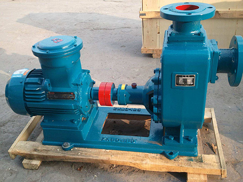
The CYZ centrifugal pump adopts an axial return liquid pump body structure, which is compos...
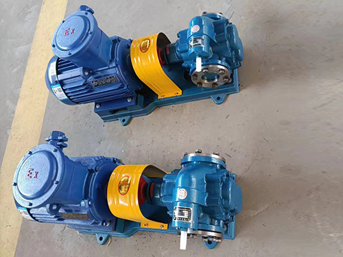
Copper gear pump (KCB type) is suitable for conveying lubricating oil or other liquids with...
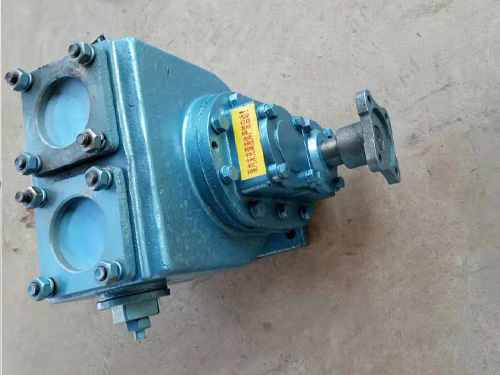
The car mounted circular arc gear pump can be installed on the car and driven by the output...